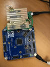
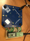
- Supplies the 3.3 V power in a nice way
- Homemade adapter gives us 16 pins that we can read or write to and then get feedback/input via P2's serial port
- Should be able to program TinyFPGA via P2,
once we figure out how...
- Trying to hack TinyFPGALoader and getting close, but not there yet
- Have open source .svf loader on Github, Lib(X)SVF, compiling with FlexC. Looks fairly easy to make that work.
- Instead of via JTAG, might be able to load via I2C or SPI (I think, maybe)
- Using pins 1..6, 9..11, and 16..22 for 16-bit bus connection to P2 Eval.
- With interface adapter connected with basepin
P0, we have:
- P2's P0..P7 connected to AX2's pins 1..6, 9 &10 (going to use these as AX2 output for P2 input, because 4 LEDS are there)
- P2's P8..P15 connected to AX2's pins 11, 16..22
- What happens if, for example, AX2 is outputting high on a pin while P2 is outputting low on same pin?
- Not really sure. Think P2 would be OK, but might fry AX2.
- To try and avoid this, thinking about using lower 8 pins and AX2 inputs only and upper 8 pins as AX2 outputs only.
- Could also put all P2 pins in pull-up and pull-down smartpin mode. This would effectively put a resistor between P2 and AX2 pins.
- But, going with a direct connection for now. Will revisit if AX2 gets fried.
- The pin names are specified in "template_a2.lpf"
-

- Edited this file inside Lattice Diamond
-

- After changing pin names, renamed this file and the .v file and then edited the project file (.ldf) in Notepad to reflect new names (so as not to get mixed up with the original), also renamed the project file to "P2Blink.ldf"
- This new project (download
here) puts the upper 8 bits of the 24 bit counter onto P0..P7 (with
adapter connected at basepin=0)
- The project shows errors on load, but works anyway. Can remove errors by changing the "input" lines to "inout", or just comment out the lines like this for the inputs (assign p2pin8 = 1'bz;). Seems that assign is only for outputs...
- My 4 leds blink faster now because they are the lower of the 8 bits being output (used to be the upper bits of 24-bit counter)
- Download first working version of this here
- Just open TinyFpga.c in FlexProp GUI and run it
-


