 |
 |
Since the contest we are continuing development of the VTD, aided by
the prize money. Here are a couple areas that we are working on:
-
Recording measured data locally to SD or uSD
-
Wireless access to recorded data
-
Battery power
-
Improved LCD interface
-
Calibration of pressure and SpO2 circuits.
-
Fixing minor errors with circuit board
|
 |
1&2: Wireless SD cards (FlashAir)
 |
The Toshiba FlashAir SD card provides us with a relatively low
cost way to have wireless access to data stored on the SD card.
(Wish it was in uSD format though since the Propeller Platform
Express board has one of those onboard.) |
 |
We originally tried EyeFi cards, but they didn't work with FSRW
or any SD card code we could find for Propeller. |
 |
Unfortunately, adding the SD card code to our project put us
over the 32kB memory limit. We are going to have to rewrite
the code from scratch to get around this... |
|
 |
3: Battery power
 |
Current thought is to add a Li-Ion-polymer battery. We'll
need a recharging circuit for this too. |
 |
We may make a new PCB for both the full size SD card slot and
the battery circuit. |
|
 |
4: Improved LCD interface
 |
We probably need to reduce the size of the graphics area to
accommodate SD card code and other improvements. Perhaps we'll
use the left side of the screen for graphics and the right side for
controls. |
 |
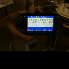
We've already added a manual Zoom control to provide 1X, 2X and
4X zoom to account for some people having smaller SpO2 signals than
others. Perhaps this can be automated in the future. |
 |
We'd like to display some info such as SpO2 percentage and
signal intensity as well. |
|
 |
5: Calibration
 |
We were able to calibrate the pressure circuit and found out
that we were a factor of 2 off. Found the error in the math
and the new code has it right. |
 |
It would be nice to calibrate the SpO2 circuit, but we'll have
to investigate how to do that. We currently have a very basic
algorithm for this based on the Freescale documentation.
|
|
 |
6: Fixing circuit board errors
 |
There were a couple of minor issues with the prototype circuit
boards that required a few jumper wires to correct. We are
currently fixing this and preparing to order a new set of boards.
|
 |

|
 |
Also, the EKG circuit was tested and an error fixed there too.
The EKG circuit is not part of this project, but was included just
because there was some extra board space and the circuitry is very
similar to the other circuits on the board. Also, there was a
spare channel on the 4-channel DAC for the EKG data.
|
|
 |
Latest code version (3A)
 |
Here is the
latest version of the code that uses the graphics area as one
big button to toggle vertical zoom between 1X, 2X and 4X.
We've also split the main code file in two with the data acquisition
cog code turned into a sub-object file to improve code readability.
|
|
|
 |
 |
This custom board provides SpO2, pressure and EKG circuits.
This board may soon be for sale.
 |
The outputs of the three circuits goes to an onboard MCP3204
(4-channel ADC) chip that provides a simple, SPI, interface to the
Propeller with the data. |
 |
The board itself is Propeller Platform compatible, and can
easily be mounted to any Propeller Platform board. Or, one can
simply use 8 wires (2 for power, 4 for SPI interface, 2 for SpO2
control) to connect this board to any microcontroller setup.
The required connections are highlighted in yellow in the layout
below: |
 |

|
|
|
![]()

