 |
Software
 |
Software is in development, but many basic test codes are already
available |
|
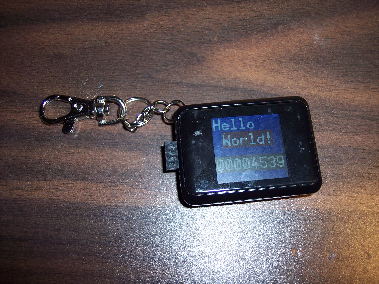
These test codes are all based on a TV-like driver. This
driver acts pretty much the same as the original Parallax driver for TV,
but outputs to the PKS LCD screen. |
|
Note: If you have a TFT screen, you'll need to make a small
change to the code to select the other driver as noted in the code
comments.
 |
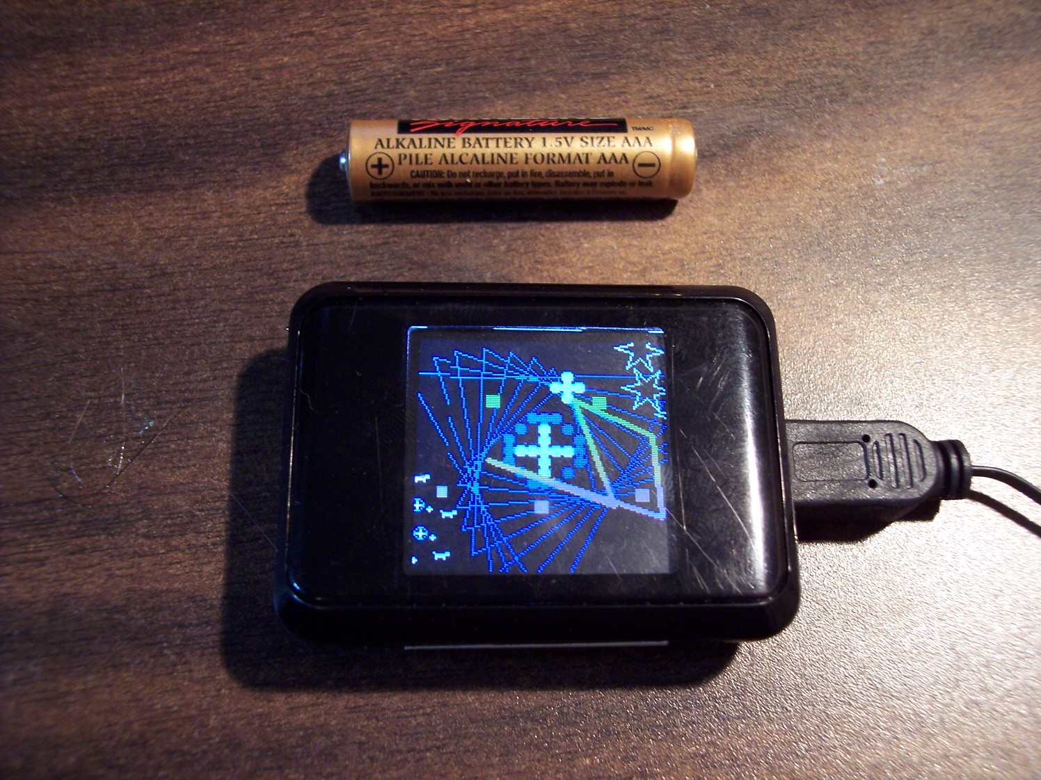
PKS Graphics Demo : A lot like the Parallax Graphics Demo
for TV, only smaller |
|
PKS Accelerometer Test
: Test the onboard 3-axis mems
accelerometer |
|
PKS Buzzer Test : Test the onboard buzzer (/speaker?)
|
|
PKS Flash Test : Test the onboard 8Mbit Flash memory chip
|
|
PKS RTC Test : Test the onboard DS1399 real time clock
chip |
|
PKS Battery Monitor Test : Test the onboard battery
voltage monitor circuit |
|
|
|
|
|
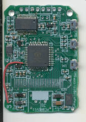
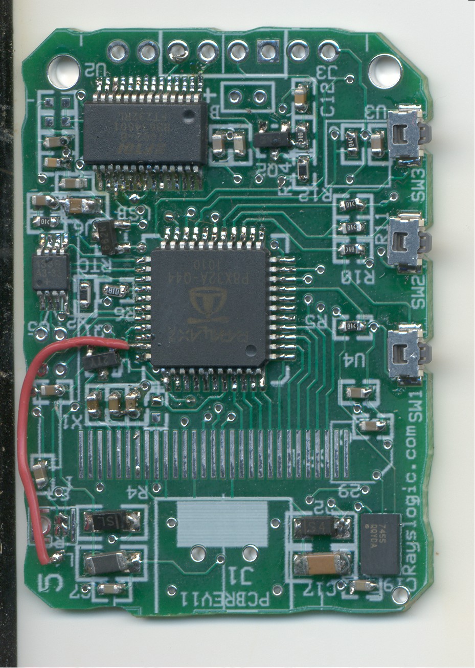
Circuit board pictures
|
Top:
|
Note: The battery voltage monitor circuit was an
afterthought, which is why it needs the jumper wire.
|
|
|
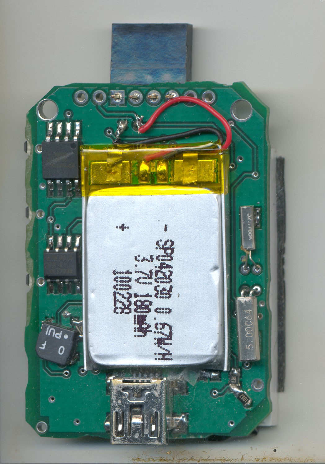
Bottom:

|
Note: The series 24 Ohm resistor for the buzzer is
an afterthought, which is why the buzzer is rotated.
|
|
|
|
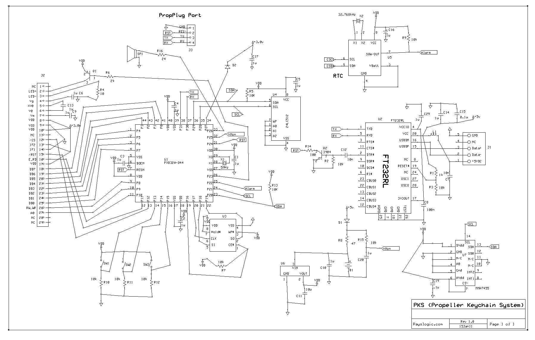
Schematic
|
Note: There is an error in the schematic concerning how the
reset line is connected to the 4-pin PropPlug port. The reset pin
at the 4-pin port is actually connected to the junction of the 100-Ohm
resistor and the collector of the NPN resistor. |
|
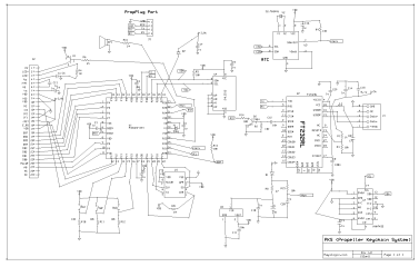 (click for full size)
 |
|
 (click for full size)