|
Reverse Engineering:
 |
These displays don't have a datasheet or schematic, so I've taken it
upon myself to reverse engineer them enough to figure out what we can
accomplish. |
|
The individual LEDs are controlled by twelve FD9802 LED controller
chips. Can't seem to get the pdf of the datasheet for it, but this
text version of the datasheet says it's
identical to the MBI5026, a 16-bit constant
current LED driver. These chips have a 16-bit register, one bit
per pixel, that turns one of 16 LEDs either off or on. The on
level current is set by the value of an external resistor.
 |
Some quick math:
|
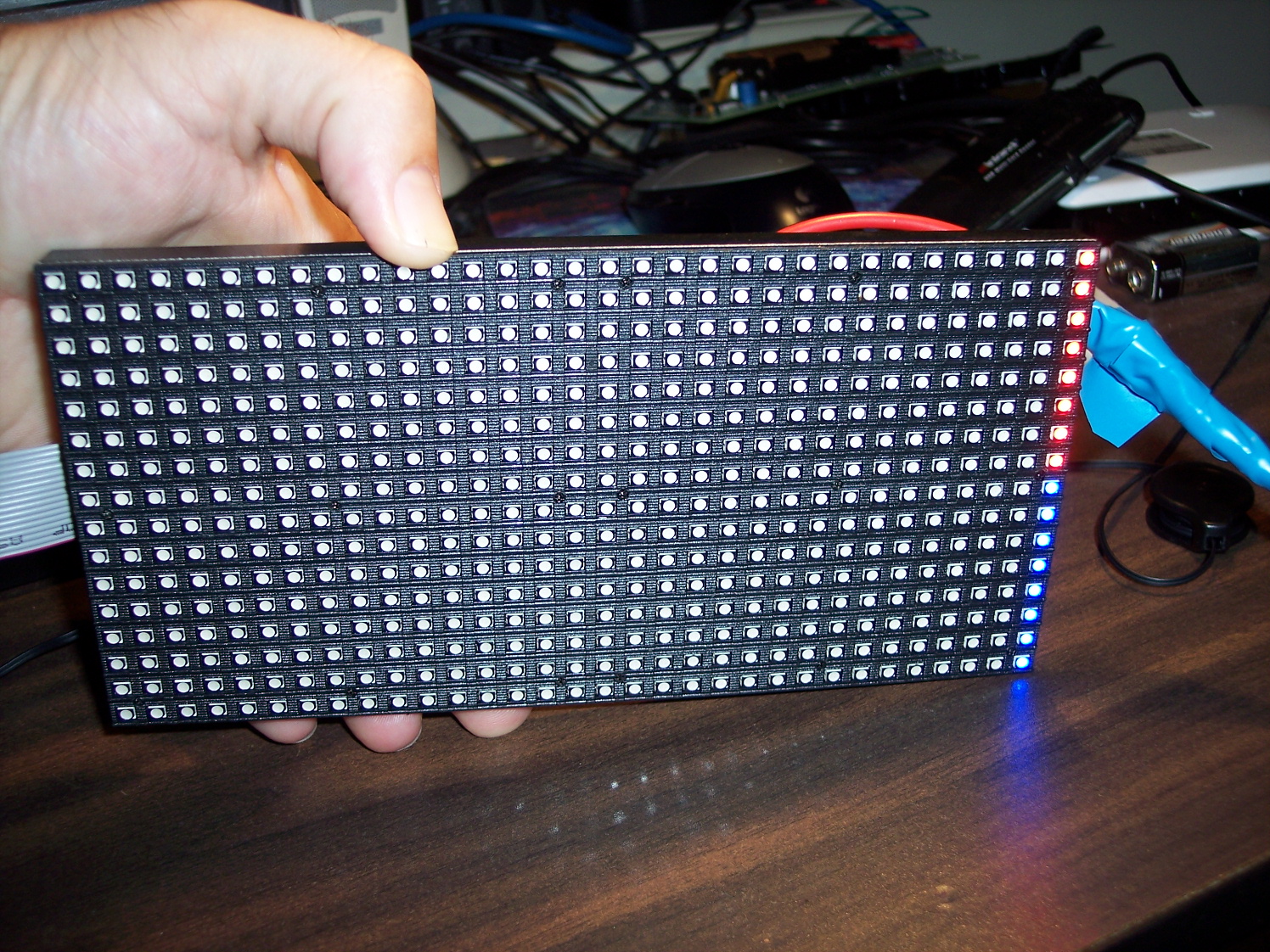
Display has 16x32x3 = 1536 LEDs to control |
|
Board has twelve 16-bit LED controlers = 12x16 = 192
<-- This is 8X less than we need! |
|
|
|
How does it control 1536 LEDs with 192 outputs? Well, there's
a 74HC138 3-to-8 demultiplexer that uses
three inputs (A, B, C) and selects one of 8 groups of pixels at a time.
This means only 1536/8 = 192 LEDs can be lit at a time. Therefore,
we have to quickly show each of the 8 groups, one at a time, quickly to
avoid flicker. Apparently, this is called "1/8 scanning" in the
LED panel business... |
|
The 74HC138 can't output enough current to control 192 LEDs, so each
of the 8 outputs of the 74HC138 goes to a
SSF4953 dual p-channel mosfet which works as a power switch.
|
|
There are six data input pins to the matrix (R1, G1, B1, R2, G2,
B2). So how do six inputs go to twelve LED controller chips?
Well, the FD9802/MBI5026 chips have a shift out as well as a shift in.
So, we shift the first 16-bits through the first chip and into the
second chip. So, in a nice way for a 32-bit MCU, we need to shift
out 32 bits to each control pin during each update of 1/8th of the
display. (Math check: 32-bits x 6-data x 8 sections = 1536 LEDs).
The data being shifted in isn't actually applied until we toggle the
"latch" signal input.
|
Note that the shift out of the second chips, as well as the ABC
control lines are connected to an output connector that allows
us to connect these displays in series. So, with two panels in
series, we'd need to shift out 64 bits for each 1/8th update.
|
|
|
There are two 74HC245 octal bus
transceiver chips that buffer all the inputs. This will allow us
to connect directly to the Prop's 3.3V outputs even though this board is
powered by +5V DC. |
|
There is also an OE, "Output Enable" input pin. This signal
fans out to all the LED controllers. This could be very useful for
sharing the same data pins with two different displays. We just
need a OE Prop output for each display. Using this along with
daisy-chaining the displays could allow a large number of displays to be
run by one Prop. |
|
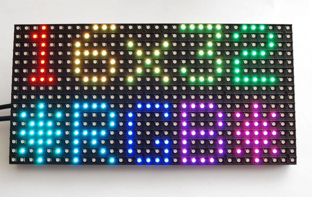
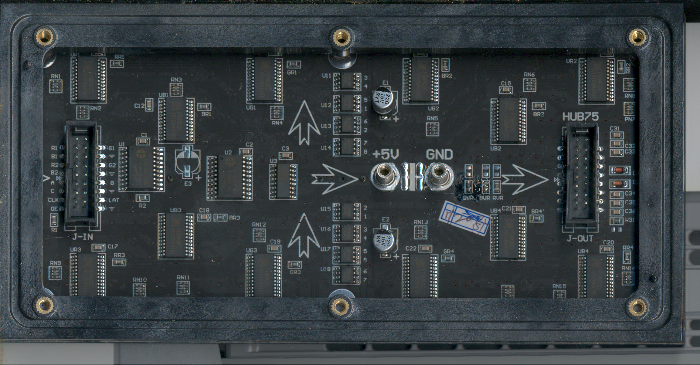
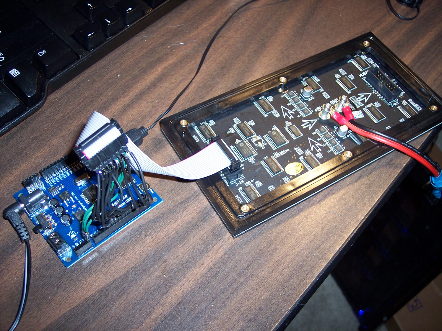
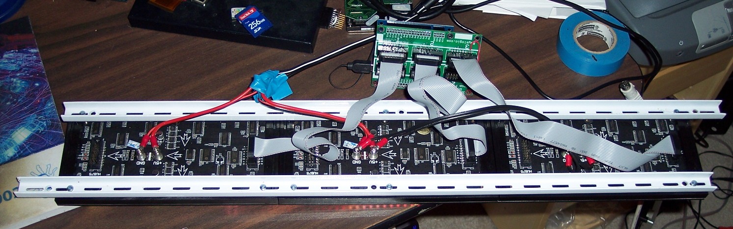
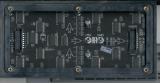
Organization/Layout:
|
You can see the 12 LED drivers in scan of the circuit board
(below). They are the large chips in kinda a zig-zag pattern
along the top and bottom of the board. I'll use the arrows
printed on the board to define "top, bottom, left, and right" for
the circuit board. For the display side, left and right are
reversed when looking from the front. |
|
|
|
The R1 input goes to the SDI input of LED driver in the top left
corner, UR1. B1 goes the the chip, UB1, a little
lower and to the right. G1 goes to the chip, UG1, back up top
and to the right of that one. The serial outputs of these
three chips go the serial inputs of UR1, UB1, and UG1 in the top
right side of the board. |
|
In the same way, the R2, B2, and G2 inputs go first to UR3, UB3,
and UG3 in the bottom-left corner and then to UR4, UB4, and UG4 in
the bottom-right corner. |
|
The benefit of having a LED driver chip just drive one color is
that each chip can have a slightly different bias current setting
resistor, in case the colors aren't exactly balanced with equal
currents. These are the RR1, BR1, and GR1 resistors in the
top-left quadrant. BR1 and GR1 are both 1000 Ohms, but RR1 is
680 Ohms. |
|
There are 16 resistor networks around the board, RN1 to RN16.
These are 8-pin units, each with four 390-Ohm resistors inside.
The purpose of these is to drop some of the voltage going to the red
LEDs. Red LEDs have a voltage drop much less than blue or
green. That means the LED driver would have to dissipate a lot
more power to drive them. Adding a resistor to each output of
the red LED driver chips, lessens the load on the driver chip.
|
|
|
Found these spec's online for what appears to be a similar unit:
|
Features
|
Parameter |
Value |
Parameter |
Value |
|
Pixel pitch |
6mm |
Driving Mode |
Constant current |
|
LED spec
&Encapsulation form |
3528/ SMD 3-in-1
|
LED Wavelength |
R:λ(625±5nm)
G:λ(520±5nm)
B:λ(470±5nm) |
|
Pixel configuration |
1R1G1B/Real pixel |
Working temperature |
-10℃--
40℃ |
|
Module size |
192mm*96mm |
MTBF |
≥10000Hours |
|
Module resolution |
32*16 |
Lifespan |
100000Hours |
|
Weight |
0.18Kg |
Smoothness |
≤1mm/≤0.5mm |
|
Scanning Mode |
1/8scanning |
Hub type |
LINSN-HUB75 |
|
Brightness |
1800cd/m2
|
Refresh frequency |
≥400Hz |
|
Power consumption |
19.2W |
Working Voltage |
DC 5V |
|
Viewing angle |
H:160°
/ V:120° |
Best view distance |
≥6-33m |
LINSN-HUB75
Interface
|
Signal
name |
Pin
number |
Description |
|
A |
9 |
The
lowest bit of row address |
|
B |
10 |
The
second lowest bit of row address |
|
C |
11 |
The
highest bit of row address |
|
LE |
14 |
Latch
of row |
|
CLK |
13 |
Clock |
|
EN |
15 |
Enable |
|
R1 |
1 |
Red data 1
|
|
R2 |
5 |
Red
data 2 |
|
G1 |
2 |
Green data 1 |
|
G2 |
6 |
Green
data 2 |
|
B1 |
3 |
Blue data 1 |
|
B2 |
7 |
Blue data 2 |
|
GND |
4,812,16 |
Grounding |
|
|
|
|
|
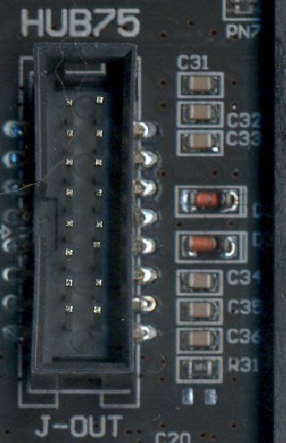
Protection Circuit:
|
All the way on the right side of the board, in the middle, is a
protection circuit that disables the de-multiplexer output unless it
senses active input. There are two diodes and some capacitors
there that rectify the "A" control signal input and apply it to the
third enable input of the 74HC138. This is probably meant to
prevent damage to LEDs if the input is not changing. |
|

|
|
|
|
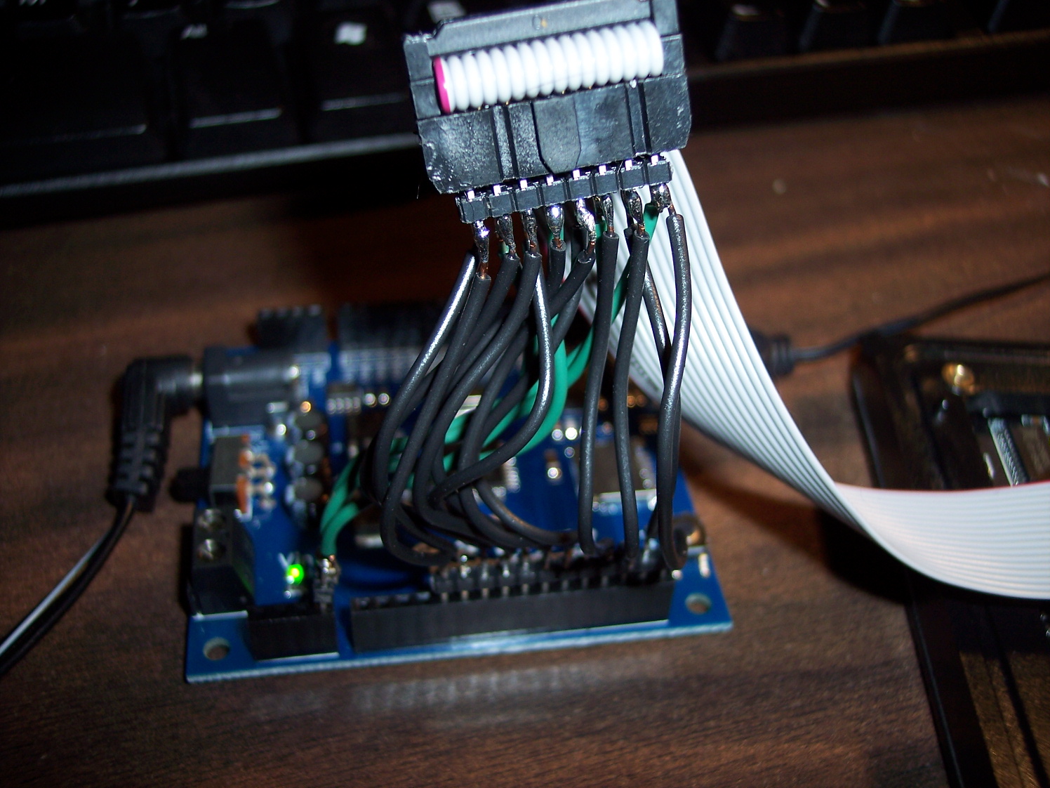
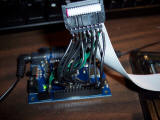
Prototyping Connections
|
Use two rows of breakaway header pins to connect black wires to
matrix's ribbon cable and then one row of breakaway header pins to plug
in to Propeller Platform USB pins P4 through P15. Also hooking up
all the grounds with green wire to the Prop Platform. |
|
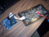
|
|
Powering with a regulated 5V, 3A switch mode supply. |
|
|
Testing it out with SPIN
|
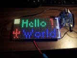
Testing with
this simple spin code lights up the last column blue and red.
|
|
This
next SPIN example lights up any one pixel white. |
|
|
Source bitmap needs to be 32x16 and 24 bits per pixel |
|
Driver only shows 3 bits per pixel though (the upper bit in each
color). So, you need to pick bright colors.
|
|
Screenshot:
|
|
Example Bitmaps:

 |
|
|
|
Assembly driver for 24 bpp (bits per pixel) color
|
The usual way to do a 24 bpp driver is to have the driver in a 256
level loop and within each loop compare the byte value of the color to
the loop# and set the output if at or above this level. But, the
Prop just isn't fast enough to get 24 bpp this way. |
|
Instead of this, we'll do a 8 bit loop with each loop lasting a
power of 2 longer. In this way, we can precalculate the output we
want in the outa register. So, there is no comparison in the loop
and it can be faster. The inner loop just does a readlong directly
to the outa register 32 times and the sets the latch. This allows
us to reach 24 bpp. Also, instead of putting in a delay for the
power of 2 time each bit loop lasts, we'll just do the inner loop a
power of 2 increasing number of times for each bit. |
|
Ghosting: In the first attempt at this, we switched between
each of the 8 sections for each bit level. But, with this display
rapidly changing between sections is a bad idea. For a reason
that's still a little unclear, if you rapidly switch between sections
there will be ghosting. The worst case was when a single LED was
lit. To resolve this, switching between sections is done in the
most outer loop so it is done as slow as possible. No ghosting is
now observed. |
|
Gamma: Well, this gets a little complicated (I'm not even sure
I understand it fully). Let me just say that without gamma
correction, bitmap images will look washed out. This is because
this driver generates 256 linear levels. But, the human eye is
non-linear. So, computer images are usually stored with levels
that linear to the eye but are non-linear in terms of how long we should
leave the LEDs on in our loop. Anyway, we need to adjust the
levels with a gamma lookup table. Level 0 still comes out as 0 and
level 255 is still 255, but levels in the middle are stretched around.
The gamma table was generated by a power function with power 2.5.
|
|
Here is the
first assembly driver example. It can show several
embedded 32x16x24bpp Windows bitmaps with 24-bit color. |
|
|
Getting serious with multiple panels and faster driver
|
Going forward, there are a few things we'd like to do...
|
Measure the current draw from each panel. We need to know
how much current these panels are drawing with this setup in order
to match the setup to the power supplies we have. |
|
Decide on how we want to hook up the multiple panels...
|
|
Fix up the driver to do more speedy bitmap updates and possibly
have inherent text scrolling ability |
|
Come up with a Windows App to test out different configurations
|
|
|
Power draw measurements:
|
Measurements with a regulated switching power supply rated for 2
A and a Fluke multimeter:
All pixels on white with
brightness=256, enable time=31: 3.0 A
Half pixels on white
with brightness=256, enable time=31: 1.5 A
All pixels on white with
brightness=256, enable time=15: 1.4 A
All pixels on white with
brightness=256, enable time=23: 2.2 A
All pixels on white with
brightness=256, enable time=7: 0.7 A
All pixels on white with
brightness=128, enable time=31: 1.5 A
All pixels on white with
brightness=64, enable time=31: 0.8 A
All pixels on white with
brightness=192, enable time=31: 2.3 A
|
These measurements indicate that brightness is linear with
the number of pixels turned on and brightness control and with
enable time control. This is good news because it means
this supply is good, even up to 3 A. Also, we can use
enable time control (or brightness control) to power multiple
panels. Enable time is probably better than brightness
control in most cases because it preserves our dynamic range.
|
|
|
|
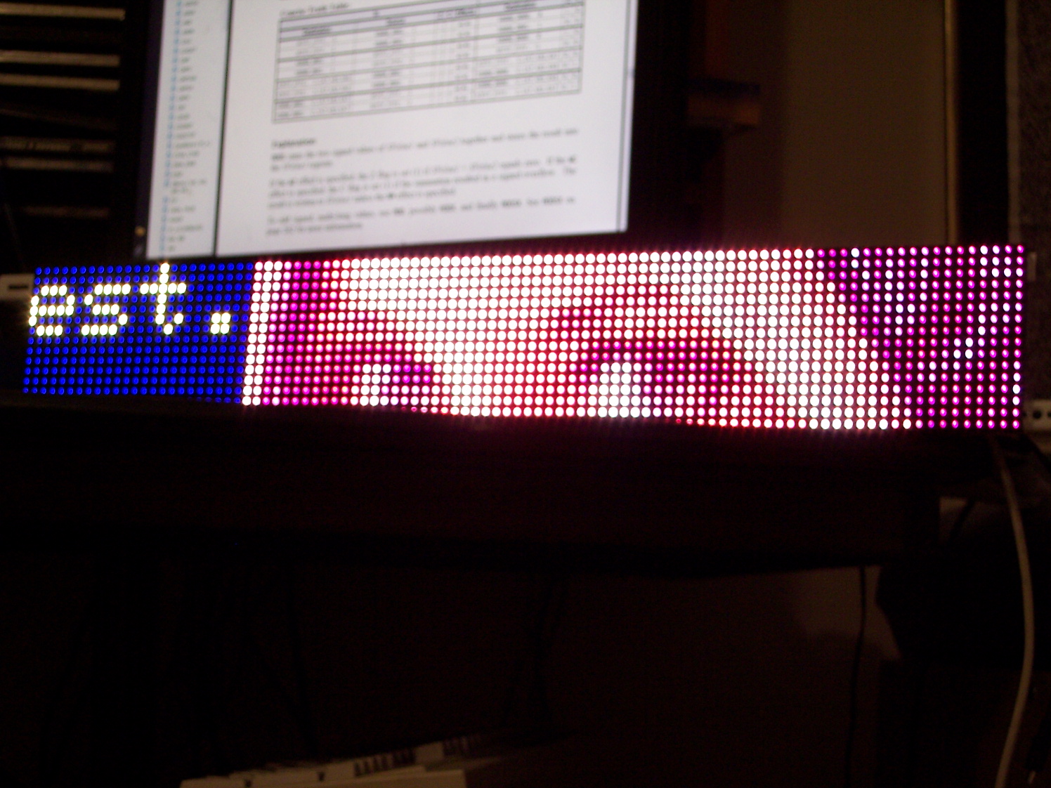
|
Demo1: Scrolling text and bitmap at same time on 3 panels with 1
Prop Platform USB
|
Screenshot:

|
|
This demo scrolls a Windows Bitmap up and down on the right side of
the screen and text on the very left side.
|
|
|
|
|
|
The assembly driver is now blazing fast and can easily support 30
FPS video over all three panels.
|
|
|
Mounting Multiple Panels
|
The mounting holes for the panels are M3 (metric screw) threads,
same as the power posts.
|
|
The simplest way I found to mount them was with brackets for
upright shelving
|
|
|
Not all the holes lined up, but enough did so that it is very
secure
|
|
|
You can get similar things at almost any hardware store
|
|
Also, the ribbon cables that came with the panels weren't all long
enough for this.
|
But, you can find longer IDC ribbon cables on Ebay for cheap
|
look for item# 180681676520 for example
|
|
|
|
For wiring, I went to the hardware store and found some lamp wire
that they sell by the foot to be a good fit.
|
Also, some ring terminals (4-6 stud, 22-18 gauge) work well for
the ends of the wire. |
|
|
|
6-Panel code example
|
This example is for 3 panels connected as shown above and then three
more, each one daisy chained to one of the original 3 to form a second
row of 16x96 pixels. |
|
|
|